

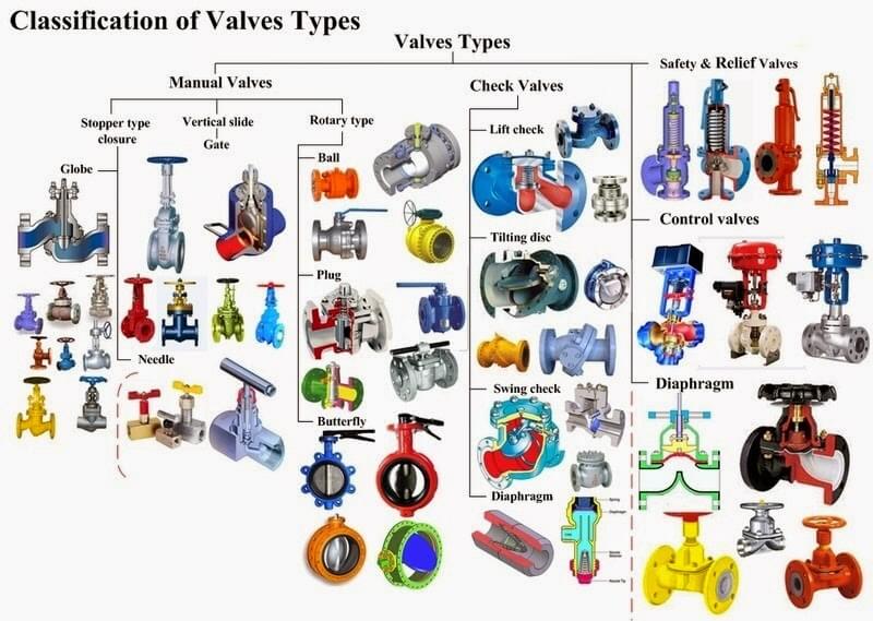
"We would rather choose a cheaper pipeline but must choose a better valve. Running, leaking, and dripping are often related to pipe fittings and valves." ———One of our big engineering project client said.

A. Select the valve according to the on-off continuity of the medium
Butterfly valve
The butterfly plate of the butterfly valve is installed in the diameter direction of the pipeline. In the cylindrical passage of the butterfly valve body, the disc-shaped butterfly plate rotates around the axis, and the rotation angle is between 0° and 90°. When the rotation reaches 90°, the valve is fully opened. The butterfly valve is simple in structure, small in size and light in weight, and consists of only a few parts. Moreover, it can be opened and closed quickly by rotating 90°, and the operation is simple. At the same time, the valve has good fluid control characteristics. When the butterfly valve is in the fully open position, the thickness of the butterfly plate is the only resistance when the medium flows through the valve body, so the pressure drop generated by the valve is small, so it has better flow control characteristics. The butterfly valve has two sealing types: elastic seal and metal seal. Elastic sealing valve, the sealing ring can be inlaid on the valve body or attached to the periphery of the butterfly plate. Valves with metal seals generally have a longer life than valves with elastic seals, but it is difficult to achieve a complete seal. The metal seal can adapt to higher working temperature, while the elastic seal has the defect of being limited by temperature. If the butterfly valve is required to be used as a flow control, the main thing is to correctly select the size and type of the valve. The structure principle of butterfly valve is especially suitable for making large-diameter valves. Butterfly valves are not only widely used in general industries such as petroleum, gas, chemical, and water treatment, but also used in cooling water systems of thermal power stations. Commonly used butterfly valves include wafer type butterfly valves and flange type butterfly valves. Wafer type butterfly valve uses double-head bolts to connect the valve between two pipe flanges. Flange type butterfly valve has flanges on the valve, and bolts are used to connect the flanges at both ends of the valve to the pipe flanges. The strength performance of the valve refers to the ability of the valve to withstand the pressure of the medium. The valve is a mechanical product that bears internal pressure, so it must have sufficient strength and rigidity to ensure long-term use without cracking or deformation.
Ball valve
The ball valve evolved from the plug valve. It has the same 90-degree rotation lifting action, but the difference is that the cock body is a sphere with a circular through hole or channel passing through its axis. The ratio of the sphere to the channel opening should be such that when the sphere rotates 90 degrees, all the spheres should appear at the entrance and exit, thus cutting off the flow. The ball valve can be closed tightly with only a 90-degree rotation and a small torque. The completely equal internal cavity of the valve provides a straight flow channel with little resistance for the medium. It is generally considered that the ball valve is most suitable for direct opening and closing, but recent developments have designed the ball valve to throttle and control the flow. The main feature of the ball valve is its compact structure, easy operation and maintenance, suitable for general working media such as water, solvent, acid and natural gas, and also suitable for media with harsh working conditions, such as oxygen, hydrogen peroxide, methane and ethylene. The ball valve body can be integral or combined.
Globe valve
The stem axis of the globe valve is perpendicular to the sealing surface of the valve seat. The opening or closing stroke of the valve stem is relatively short, and it has a very reliable cut-off action, making this valve very suitable for the cut-off or adjustment and throttling of the medium. Once the valve disc of the shut-off valve is in the open condition, there is no longer contact between its valve seat and the sealing surface of the valve disc, and has a very reliable cut-off action. This kind of valve is very suitable for cutting or regulating and reducing the medium. Stream usage. Once the shut-off valve is in the open state, there is no contact between its seat and the sealing surface of the disc, so its sealing surface is less mechanically worn, because most of the shut-off valve seats and discs are easier to repair or replace It is not necessary to remove the entire valve from the pipeline when sealing the components, which is very suitable for the occasion where the valve and the pipeline are welded together. The flow direction of the medium through this type of valve has changed, so the flow resistance of the stop valve is higher than that of other valves. Commonly used shut-off valves are as follows: 1) Angle type shut-off valve; in the angle type shut-off valve, the fluid only needs to change its direction once, so that the pressure drop through this valve is smaller than that of the conventional structure of the shut-off valve. 2) Direct-flow stop valve; in direct-flow or Y-shaped stop valve, the flow passage of the valve body is in a diagonal line with the main flow passage, so that the degree of damage to the flow state is smaller than that of the conventional stop valve, so the pressure loss through the valve is also corresponding Is too small. 3) Plunger type globe valve: This type of globe valve is a variation of the conventional globe valve. In this valve, the disc and valve seat are usually designed based on the plunger principle. The valve clack is polished so that the plunger and the valve stem are connected, and the sealing is achieved by two elastic sealing rings sleeved on the plunger. The two elastic sealing rings are separated by a sleeve ring, and the sealing ring around the plunger is pressed firmly by the load exerted on the bonnet by the bonnet nut. The elastic sealing ring can be replaced and can be made of various materials. The valve is mainly used for "open" or "close", but it is equipped with a special form of plunger or special collar, which can also be used to adjust flow .
Gate valve
The gate valve is used as a cut-off medium, and the whole flow is straight when it is fully opened. At this time, the pressure loss of the medium is minimal. Gate valves are usually suitable for working conditions that do not need to be opened and closed frequently and keep the gate fully open or fully closed. Not suitable for use as regulation or throttling. For the high-speed flowing medium, the gate can cause vibration of the gate when it is partially opened, and the vibration may damage the sealing surface of the gate and the valve seat, and the throttling will cause the gate to be eroded by the medium. From the structural form, the main difference is the form of the sealing element used. According to the form of sealing elements, gate valves are often divided into several different types, such as: wedge gate valve, parallel gate valve, parallel double gate valve, wedge double gate valve, etc. The most commonly used forms are wedge gate valves and parallel gate valves.
B. Select the valve according to the prevention of medium backflow
The function of this type of valve is to only allow the medium to flow in one direction, and to prevent the flow of the direction. Usually this kind of valve works automatically. Under the action of the fluid pressure flowing in one direction, the valve flap opens; when the fluid flows in the opposite direction, the fluid pressure and the self-coincidence of the valve flap act on the valve seat to cut off the flow. Among them, the check valve belongs to this type of valve, which includes swing check valve and lift check valve. The swing check valve has a hinge mechanism and a valve disc like a door that rests freely on the inclined valve seat surface. In order to ensure that the valve clack can reach the proper position of the valve seat surface every time, the valve clack is designed in a hinge mechanism so that the valve clack has enough space for turning and makes the valve clack truly and comprehensively contact the valve seat. The valve clack can be made of metal, leather, rubber, or synthetic covering can be inlaid on the metal, depending on the performance requirements. When the swing check valve is fully opened, the fluid pressure is almost unimpeded, so the pressure drop through the valve is relatively small. The valve disc of the lift check valve is seated on the sealing surface of the valve seat on the valve body. Except that the disc can be raised and lowered freely, the rest of this valve is like a shut-off valve. The fluid pressure lifts the disc from the seat sealing surface, and the backflow of the medium causes the disc to fall back onto the seat and cut off the flow. According to the conditions of use, the valve clack can be an all-metal structure, or it can be in the form of a rubber pad or a rubber ring inlaid on the valve clack frame. Like a shut-off valve, the passage of fluid through the lift check valve is also narrow, so the pressure drop through the lift check valve is larger than that of the swing check valve, and the flow rate of the swing check valve is restricted rarely.
D. Select the valve according to the nature of the valve drive
Electrically driven valves
Electric drive valve is a commonly used drive mode valve. This drive device is usually called a valve electric device. The characteristics of the valve electric device are as follows: 1) Open and close quickly, which can greatly shorten the time required to open and close the valve; 2) It can greatly reduce the labor intensity of the operator, especially suitable for high-pressure, large-diameter valves; 3) Suitable for installation in locations that cannot be manually operated or difficult to access, easy to achieve long-distance operation, and the installation height is not limited; 4 1) Conducive to the automation of the entire system; 5) Power is easier to obtain than air and liquid sources, and the laying and maintenance of its wires is much simpler than compressed air and hydraulic pipelines. The disadvantage of the valve electric device is its complex structure, and it is more difficult to use it in humid places. When used in explosive media, explosion-proof measures are required. Valve electric devices can be divided into two categories: Z-type and Q-type according to the type of valve they drive. The output shaft of the Z-type valve electric device can rotate many times, which is suitable for driving gate valves, stop valves, diaphragm valves, etc.; the output shaft of the Q-type valve electric device can only rotate 90 times. Suitable for driving plug valves, ball valves and butterfly valves, etc. According to its protection type, there are ordinary type, explosion-proof type (represented by B), heat-resistant type (represented by R) and three-in-one type (ie outdoor, anti-corrosion, explosion-proof, represented by S). The valve electric device is generally composed of a transmission mechanism (reducer), a motor, a stroke control mechanism, a torque limit mechanism, a manual-electric switching mechanism, and an opening indicator.
Pneumatic and hydraulic valves
Pneumatic valves and hydraulics use a certain pressure of air, water or oil as the power source, and use the movement of cylinders (or hydraulic cylinders) and pistons to drive the valves. Generally, the pneumatic air pressure is less than 0.8MPa, and the hydraulic water pressure or The oil pressure is 2.5MPa~25MPa. Or diaphragm valve; the rotary gas and liquid drive device is used to drive the ball valve, butterfly valve or plug valve. The hydraulic device has a large driving force and is suitable for driving large-caliber valves. If it is used to drive plug valves, ball valves and butterfly valves, the reciprocating motion of the piston must be converted into a rotary motion. Except for the use of pneumatic cylinders or pistons of hydraulic cylinders to drive, there is no pneumatic film drive. Because of its small stroke and driving force, it is mainly used for regulating valves.
Manual valve
Manual valve is the most basic drive valve. It includes direct drive by handwheel, handle or wrench and drive by transmission mechanism. When the opening torque of the valve is large, it can be driven by gear or worm gear to achieve the purpose of omission. Gear transmission is divided into spur gear transmission and bevel gear transmission. The gear transmission has a small reduction ratio, which is suitable for gate valves and globe valves, and the worm gear transmission has a relatively large reduction ratio, which is suitable for cock flashes, ball valves and butterfly valves.